Calculating the total delay
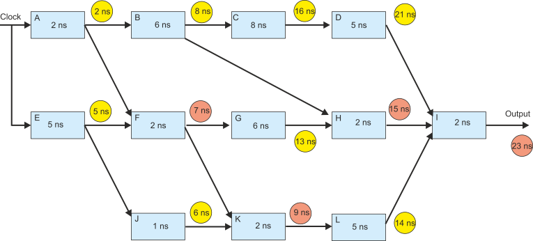
The figure below gives the delays of signals passing through the blocks from the initial clock pulse.
A yellows circle shows the simple algebraic sum of times; for example, the output of block C is labeled 16 ns because the delay is 2 + 6 + 8 = 16 ns.
Notice the output of block F. This is in red because it indicates that there are two or more paths involved and we must take the longest delay. In this care the input to F comes from block E (5 ns) and from block A (2 ns). The longer path is from E and therefore the output delay is 5 + 2 = 7 (i.e., the longest input path plus the delay of 2 itself). The final output appears after 23 ns.
If you follow this link you can examine a timing diagram for this system.
We can’t improve on this value without modifying the circuit. But, we can use pipelining to improve the average throughput for a sequence of inputs.